SEM Pathology
Contents
1. What is SEM ?
※Unauthorized reproduction of any text, image, or other content of this Website is prohibited.
An introduction
1. What is SEM ?
There are two types of electron microscopes; one is SEM*1 and the other is TEM*2. Both are for observation of fine sample structures at high magnification, particularly near the sample surface with SEM and mainly in the sample interior with TEM.
Here, we describe the distinguishing characteristics of SEMs.
*1 SEM:Scanning Electron Microscope
*2 TEM:Transmission Electron Microscope
Features of SEM
- Observation of any solid surface from low to high magnification.
- Stereoscopic imaging with far greater depth of focus*3 than light microscopes.
- Elemental analysis of micro regions when used in combination with an X-ray analyzer.
*3 Depth of focus (DoF): When relatively thick samples is observed, “Deep DoF” means, focusing at considerable depth within the sample, and “Shallow DoF” does focusing only near the sample surface.
This figure shows the resolution that can be obtained by the human eye, a light microscope, and an electron microscope. Resolution is the shortest distance between two objects that can be seen as separate. It is about 0.1~0.2 mm for the human eye. For still smaller distances, a light microscope or electron microscope is required to magnify the image. The sample is illuminated by light under a light microscope and irradiated by a beam of electrons in an electron microscope.
Typical SEM observations
The following are typical images of animal tissue obtained by SEM.
To prepare typical animal tissue containing water for high-vacuum SEM observation, the sample is pre-processed by fixation, dehydration, drying, and metal coating.
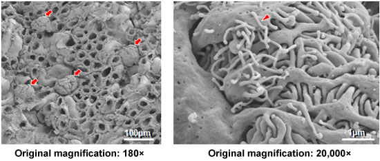
Rat renal glomerulus
In the low-magnification image on the left, the renal glomeruli ( ) appear round. The higher-magnification image on the right clearly shows the fern-like inter-entanglement of podocytes and a microvillus (
 ) of indeterminate length.
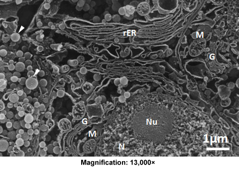
Rat subcellular organelles
This 3D image of a cryo-fractured sample clearly shows rat subcellular organelles, including the nucleus (N), nucleolus (Nu), rough endoplasmic reticulum (rER), Golgi apparatus (G), and mitochondria (M), together with secretory granules (arrowheads).
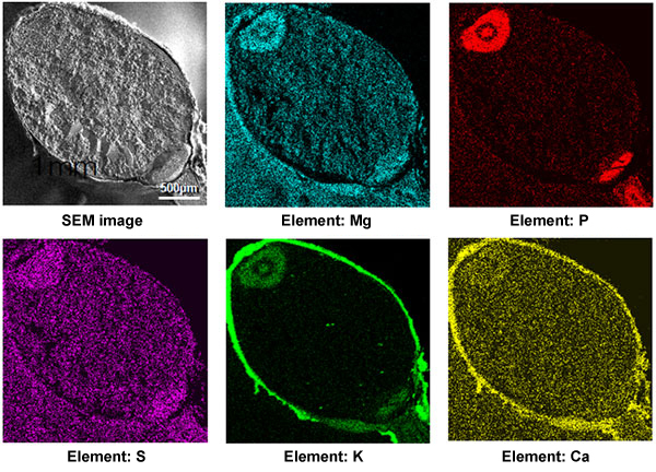
Typical elemental analysis
The following are cross-sectional images of a seed of a quinoa plant, a member of the goosefoot genus (dicot). Quinoa seeds are used as a foodstuff high in proteins and minerals. In elemental analysis, images such as these show the distribution of magnesium (Mg), phosphorus (P), sulfur (S), potassium (K), calcium (Ca), and other minerals.
(2) Principle and structure of SEM
What is SEM ?
An SEM scans the sample surface in a vacuum with a narrow electron beam, gathers information (signals) emitted from the sample, and forms a magnified image of the sample surface on the display screen.
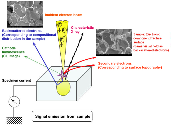
Under irradiation by the narrow electron beam in a vacuum, the sample emits secondary electrons, backscattered electrons, characteristic X-rays, and other waves or particles, as shown above. In the SEM, the images are formed mainly from the secondary- or backscattered-electron signals. Secondary electrons are emitted from near the surface of the sample, and the image formed from them represents the sample surface.
Backscattered electrons are electrons that are bounced back by atoms composing the sample. The higher the atomic number of the atoms in a component, the larger the number of emitted electrons. The contrast in a backscattered-electron image thus depends on the average atomic number of each component (compositional contrast), and the image can therefore show the compositional distribution in the sample.
An SEM can also be used for elemental analysis to identify the elements in the sample by attaching an X-ray detector.
SEM structure
As shown in the following figure, SEM consists of electron-optical column mounted on sample chamber, display unit and control unit. A vacuum is maintained in the column, electrons are emitted from an electron gun, and the electron beam is narrowed and focused onto the sample surface by electromagnetic lenses such as condenser lens and objective lens. Scan signal is applied to deflection coil to scan electron beam on the sample surface. The sample chamber accommodates sample translation stage and various detectors to detect secondary electrons, backscattered electrons and x-rays emitted from the sample. A vacuum pump is connected below the sample chamber to evacuate the column and the sample chamber, thus maintaining the vacuum.
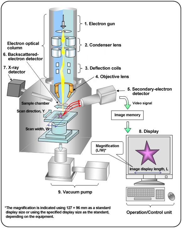
The function of each component is described below.
- Electron gun
Ejects and accelerates electrons from a metal in a strong electric field. - Condenser lens
Electromagnetic lens (coil) that narrows the electron ejection of the electron gun to an electron beam. - Deflection coil
Causes the electron beam to scan in the X and Y directions and controls the scan area (and thus the magnification). As shown in the figure, the SEM magnification is determined by the ratio of the width, L, of the image displayed on the screen to the width, W, of the electron beam scan. - Objective lens
Narrows the electron beam and focuses it onto the sample surface. - Secondary-electron detector
Detects the secondary electrons emitted by the sample and forms an image corresponding to the sample surface topology. - Backscattered-electron detector
Detects electrons backscattered from the sample, which correspond to the compositional distribution at the sample surface. Can also provide information on surface roughness. - X-ray detector
Detects X-rays emitted from the sample, which can be used to determine the elements in the sample and their quantities. - Display
Displays secondary-electron image, backscattered-electron image, and the results of X-ray analyses. - Vacuum pump
Evacuate the column and the sample chamber and maintain the vacuum.
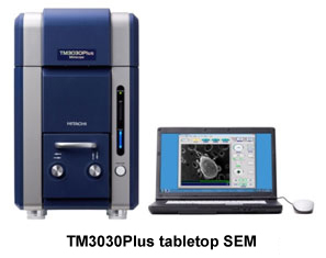
(3) Nice things about tabletop SEM
Compared with ordinary high-vacuum SEMs, a tabletop SEM is small enough to use on a tabletop (thus called “tabletop SEM”), needs only a 100-V power supply, and is easy to operate, even for beginners. Low vacuum capability enables observation of nonconductive samples such as papers and plastics and those containing water and oil reducing or eliminating the need for sample preparation. Elemental analysis can be performed on models equipped with an internal X-ray detector. The desktop SEM is commonly used to observe backscattered-electron images, but it can also be used to observe secondary-electron images by attachment of a low-vacuum secondary-electron detector.
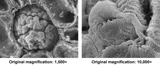
Rat renal glomerulus – 1 (secondary electron images)
These are low-vacuum secondary-electron images of a renal glomerulus sample prepared for ordinary high-vacuum SEM observation. The image on the left shows the whole glomerulus. The image on the right shows part of it at a higher magnification, in which the intertangling of podocytes and other components is clearly visible.
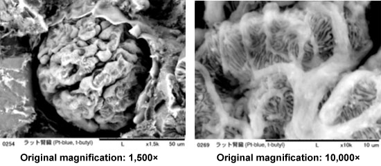
Rat renal glomerulus – 2 (backscattered-electron images)
An animal tissue block can be observed by low vacuum SEM with simplified preparation; chemical fixation followed by platinum-blue staining omitting metal coating.
These are low-vacuum backscattered images of rat renal tissue fixed only by GA, stained with platinum-blue, and dehydrated and freeze-dried with t-butyl. They were taken without metal coating. The backscattered-electron images differ somewhat in appearance from the above secondary-electron images, but the intertangled foot processes of podocytes and other components are again clearly visible.
※Unauthorized reproduction of any text, image, or other content of this Website is prohibited.
